Mathematical fidelity: These page images preserve the exact notation and visual layout of the supplied PDF. The optional text extract below is for searching/copying only and may contain transcription errors.
Original pages — equations and symbols preserved

Show extracted text (searchable; equations may be imperfect)
Extract · PDF page 1
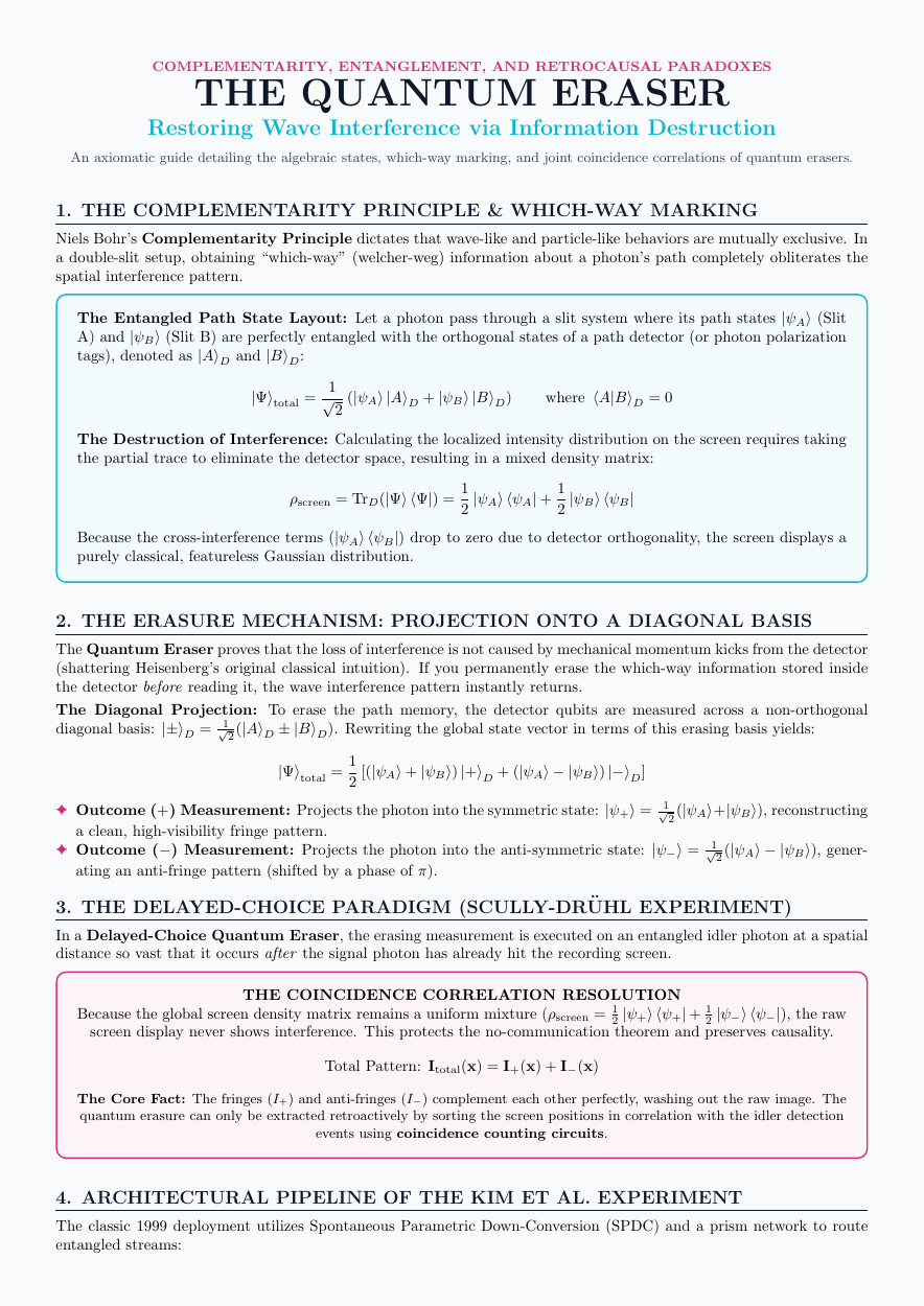
COMPLEMENTARITY, ENTANGLEMENT, AND RETROCAUSAL PARADOXES
THE QUANTUM ERASER
Restoring Wave Interference via Information Destruction
An axiomatic guide detailing the algebraic states, which-way marking, and joint coincidence correlations of quantum erasers.
Extract · PDF page 1
1. THE COMPLEMENTARITY PRINCIPLE & WHICH-WAY MARKING
Niels Bohr’s Complementarity Principle dictates that wave-like and particle-like behaviors are mutually exclusive. In
a double-slit setup, obtaining “which-way” (welcher-weg) information about a photon’s path completely obliterates the
spatial interference pattern.
The Entangled Path State Layout: Let a photon pass through a slit system where its path states |ψA⟩(Slit
A) and |ψB⟩(Slit B) are perfectly entangled with the orthogonal states of a path detector (or photon polarization
tags), denoted as |A⟩D and |B⟩D:
1
|Ψ⟩total = √ (|ψA⟩|A⟩D + |ψB⟩|B⟩D) where ⟨A|B⟩D = 0
2
The Destruction of Interference: Calculating the localized intensity distribution on the screen requires taking
the partial trace to eliminate the detector space, resulting in a mixed density matrix:
1 1
ρscreen = TrD(|Ψ⟩⟨Ψ|) = |ψA⟩⟨ψA| + |ψB⟩⟨ψB|
2 2
Because the cross-interference terms (|ψA⟩⟨ψB|) drop to zero due to detector orthogonality, the screen displays a
purely classical, featureless Gaussian distribution.
Extract · PDF page 1
2. THE ERASURE MECHANISM: PROJECTION ONTO A DIAGONAL BASIS
The Quantum Eraser proves that the loss of interference is not caused by mechanical momentum kicks from the detector
(shattering Heisenberg’s original classical intuition). If you permanently erase the which-way information stored inside
the detector before reading it, the wave interference pattern instantly returns.
The Diagonal Projection: To erase the path memory, the detector qubits are measured across a non-orthogonal
diagonal basis: |±⟩D = √12(|A⟩D ± |B⟩D). Rewriting the global state vector in terms of this erasing basis yields:
1
|Ψ⟩total = [(|ψA⟩+ |ψB⟩) |+⟩D + (|ψA⟩−|ψB⟩) |−⟩D] 2
✦Outcome (+) Measurement: Projects the photon into the symmetric state: |ψ+⟩= √12(|ψA⟩+|ψB⟩), reconstructing
a clean, high-visibility fringe pattern.
✦Outcome (−) Measurement: Projects the photon into the anti-symmetric state: |ψ−⟩= √12(|ψA⟩−|ψB⟩), gener-
ating an anti-fringe pattern (shifted by a phase of π).
Extract · PDF page 1
3. THE DELAYED-CHOICE PARADIGM (SCULLY-DR¨UHL EXPERIMENT)
In a Delayed-Choice Quantum Eraser, the erasing measurement is executed on an entangled idler photon at a spatial
distance so vast that it occurs after the signal photon has already hit the recording screen.
THE COINCIDENCE CORRELATION RESOLUTION
Because the global screen density matrix remains a uniform mixture (ρscreen = 12 |ψ+⟩⟨ψ+| + 12 |ψ−⟩⟨ψ−|), the raw
screen display never shows interference. This protects the no-communication theorem and preserves causality.
Total Pattern: Itotal(x) = I+(x) + I−(x)
The Core Fact: The fringes (I+) and anti-fringes (I−) complement each other perfectly, washing out the raw image. The
quantum erasure can only be extracted retroactively by sorting the screen positions in correlation with the idler detection
events using coincidence counting circuits.
Extract · PDF page 1
4. ARCHITECTURAL PIPELINE OF THE KIM ET AL. EXPERIMENT
The classic 1999 deployment utilizes Spontaneous Parametric Down-Conversion (SPDC) and a prism network to route
entangled streams:
Extract · PDF page 2
1. SPDC Generation: An ultraviolet laser hits double slits, creating entangled pairs: |Ψ⟩∝|slit1⟩s |slit1⟩i +
|slit2⟩s |slit2⟩i.
Extract · PDF page 2
2. Signal Path: Signal photons (s) head directly to detector D0 to record impact coordinates.
3. Idler Path: Idler photons (i) route through 50/50 beam splitters. Reaching detectors D1 or D2 completely erases
which-way histories, while reaching D3 or D4 preserves the original path trajectory.